
External EC-47 Modifications
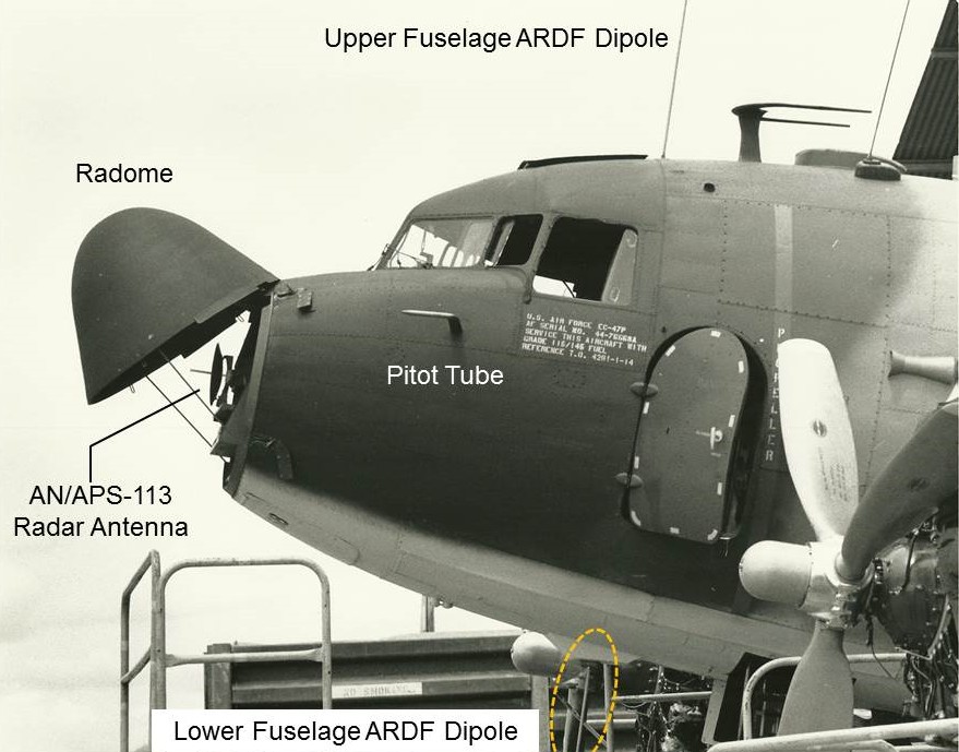
To any but the keenest observer, there was very little about the EC-47 to distinguish it from the World War II “Gooney Bird.” The most obvious differences were the elongated radome and the various antennas sprouting from the wings and fuselage. An upgraded rotating beacon was mounted atop the vertical stabilizer. Presumably to avoid interference with the ARDF dipoles, the pitot tubes were removed from the original location beneath the nose and relocated to the sides of the fuselage, just under the cockpit side windows.
The photo below, taken by Norm Taylor, shows the forward fuselage of an Electric Goon undergoing maintenance. Note the sliding windows, dashed yellow lines around the emergency escape hatch, the red propeller warning stripe, and the Hamilton Standard logo on the propellers.
One other small modification was made to the airframe. A leaflet chute was installed in the rearmost window opening on the right-side fuselage. In order to disguise the real mission, propaganda leaflets were to be dispersed from this chute, making the EC-47 appear to be a psychological warfare bird. (Which was in fact another chore performed by the versatile Gooney Bird.) After some early experimentation, leaflet dropping was discontinued, although the chute continued to occasionally serve as a convenient disposal point for cigarette butts or other small debris.
Another modification, almost invisible, was the replacement of the WWII navigator's "astrodome" by a flat sheet of clear plexiglass. The annular astrodome base, visible just underneath the U-shaped antenna in the photo, remained in place.
Antennas
The various antennas on the EC-47N and P models are shown in this diagram from T.O. 1C-47(E) N-1, Partial Flight Manual for the EC-47 aircraft series, universally known as the “Dash one.” The figure shows the antenna configuration for the five aircraft fitted with the QRC-346 electronic warfare (jamming) suite.
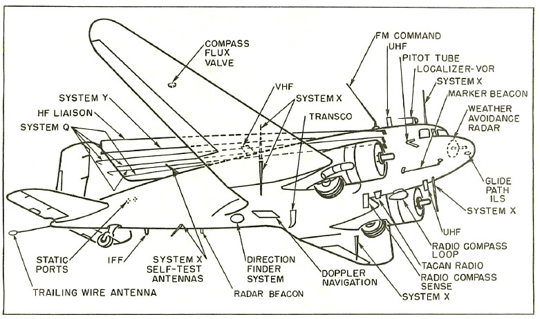
Normally, only two long wire antennas were mounted, rather than the “banjo” array of six shown here. Likewise, the retractable trailing wire was installed only on those aircraft with the “Q” jamming system. Those EC-47Q models equipped with the VHF-capable AN/ALR-38 system mounted an ARDF antenna array which differed markedly from the dipoles of the ALR-34 and 35 systems on the N and P models. (Labelled as "System X" in the diagram above.) The AN/ALR-38 configuration is illustrated below.
The EC-47Q
Not to be confused with the EC-47N aircraft carrying the QRC-346 system, the Q model of the EC-47 was fitted with more powerful Pratt & Whitney R-2000-4 engines, versus the original P&W R-1830s installed on the N and P models. Only sixteen Q models were models were produced. The R-2000s were fitted with slightly different propellers than the R-1830s, although it would take a sharp eye indeed to detect the difference. What did catch the eye was the protrusion of the prop away from the engine. This was due, not to a longer shaft, but a difference in the propeller attachment mechanism. In addition to the standard communication and navigation antennas carried on N and P models, the EC-47Q was equipped with a completely different ARDF antenna array, as shown below.
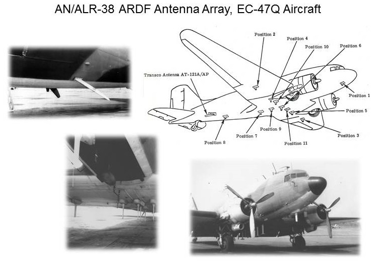
In the right-most photo above, note the thinner propeller blades near the hub as compared to the "paddle" props on N ad P models. Below is EC-47Q serial number 43-48636 while assigned to the 362nd TEWS at Da Nang. The protruding propellers and VHF-spectrum ARDF antennas are clearly visible, and the pneumatic deicer boots appear to remain installed on both vertical and horizontal stabilizers.

This aircraft, operating under the tactical callsign BARON 52, was shot down over Laos on 5 February 1973, the last of five USAF EC-47s to be lost to enemy action while in flight. (Photo by Norm Taylor.)
Note: For details concerning any particular aircraft, see EC-47 Serial Numbers and Data elsewhere on the site.
Article by Joe Martin
30 July 2015