
The Instrument Panel
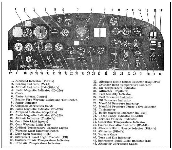
A typical EC-47 instrument panel layout, extracted from the “Dash One”, is shown below. The most noticeable difference in the updated EC-47 instrument panel was the weather avoidance radar screen in the center. (Item #8 below.) The installation of this screen necessitated the removal of the autopilot—the Electric Goon was hand-flown all the way. Another noticeable addition was the Heading Indicator, or gyro compass (#2). The ID-250 Radio Magnetic Indicator (#4) was an integral part of the ARDF system.
The Radio Control Panel
In the “brow” of the cockpit, jus above the windows, were the controls for the various communication radios, the AN/UPN-25 Identify Friend or Foe/Selective Identification Feature (IFF/SIF) transponder, and the associated "coders." The IFF/SIF enabled friendly radar sites to identify and track individual aircraft through encrypted responses.
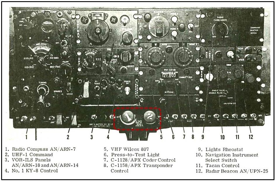
The large knobs marked “1” and “2” were the propeller feathering controls for the left and right engines, respectively. The shape directly underneath them is the top of the center window post.
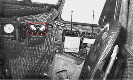
The Rest of the Cockpit
The photo below illustrates some additional details not shown in the instrument panel diagram, particularly the “whiskey” compass centered above the instrument panel. Note the pipe on the “dashboard”. The left-hand windshield wiper is also visible, as are pair of USAF-issue sunglasses hanging from the compass bracing. The extreme wear on the co-pilot's right rudder pedal is interesting.
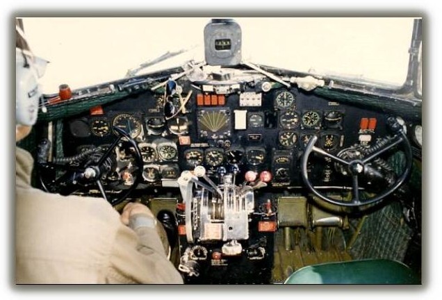
The left-most pair of knobs (white) set the propeller pitch, and thus engine RPM. The middle set, black but somewhat indistinct here, are the throttles. Pushing the throttle forward increased manifold pressure, providing more engine torque and thrust, transferred through the “constant speed” propeller, which changed pitch as required to maintain a steady RPM for optimum performance. The right hand set (red) are fuel mixture controls. There were four settings, back to front: Idle/cut off, auto lean, auto rich, and full rich. Tightening the large knob dircectly underneath set throttle friction so that desired power settings could be maintained.
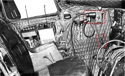
The views below, also from the Dash One, show the cockpit sidewalls. The numbers refer to the AIC-10 radio/interphone selector controls, which will be shown in detail elsewhere. The fore-aft trim wheel can be seen in the left side view. The quilted insulation was mainly for noise reduction.
 |
 |
The uppermost dashed box in the left view marks the pilot’s flexible “map light” and rheostat control. The lower box surrounds the connector for the pilot’s headphones. In the right hand view, the cowl flap controls are marked. (Settings: Open, for maximim airflow around the cylinders; closed, to hold in heat for cold weather starts; or "trail", freely moving to present minimum drag.) Just to the left, but almost invisible, is the co-pilot’s map light. The large dial just beyond is the hydraulic system pressure gage.
__________
Thanks to Chuck Miller and Allen Simmons, former Gooney Bird pilots, for help with this page.
Article by Joe Martin
06 August 2015